Our partners


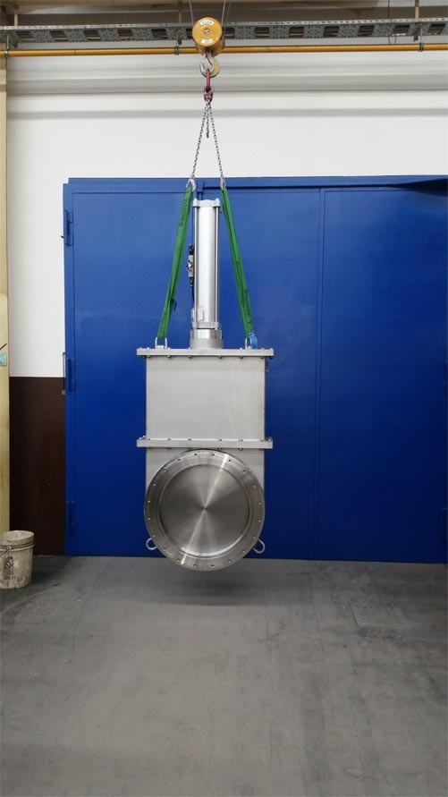
Water cooled vacuum gate valve

Applications:
- Rough, fine and high Vacuum
- Vacuum pumping units and vacuum plants to build up material locks
- Sealing unit for the suction side of a diffusion pumps
Model: The gate valve disk is water cooled, to reduce radiant heat.
Abmessung

Operating pressure: 10-3 mbarabs bis 0,5 bar ü
Max. Allow. differential pressure (from both sides): 1,5 bar
Leak tightness - body: < 1 x 10⁻⁴ [mbar l/s]
Leak tightness - disk: < 1 x 10⁻⁵ [mbar l/s]
Max. Allowable Temperature::
- Housing ≤ 120 °C
- Drive ≤ 60 °C
- Control valve ≤ 50 °C
Material – valve disk: SS 304L
Material – valve disk seal: VITON
Surface outside::
Stainless steel gate valves are shot blasted mild steel gate valves are sand blasted, prepared and painted, RAL 7035 or colour to request.
Technische Details
| Diameter DN | mm | 600 |
|---|---|---|
| 600 | mm | 2440 |
| Dimension B | mm | 900 |
| Dimension C | mm | 250 |
| Dimension D | mm | 300 |
| Dimension E | mm | 1440 |
| Dimension F | mm | 740 |
| Dimension G | mm | 20 x M16 |
| Weight | kg | 600 |
| Part Number | Mild steel | WER 02056.ST.WK.02 |
| Part Number | Stainless steel | WER 02056.VA.WK.02 |
Options: O-Ring grooves in the connection flange und dimension F/G can be made to customer request.
Installation instructions
The installation position of the disk is very important and care should be taken to make sure that the vacuum area to be sealed lays over the valve disk. The installation should only be carried out under clean conditions of a level that is usual for vacuum technology. If installation is carried out in an incorrect, dirty way and this causes unsatisfactory operation we will accept no responsibility under guarantee.
Torque for the flange screws
| Diameter DN | Torque |
|---|---|
| 600 | ~ 70 – 90 Nm |
The flange screws must be tightened equally and in a crosswise manner. Higher torques can deform the housing so much that the valve can no longer be properly operated or the valve seat may leak.
Outside effects
Outside effects Additional effects such as those caused by items attached to the valve are to be avoided. Connection by items such as bellows is to be avoided.
Max. Allowable effects:
| Diameter DN | Axial pull-/pushing effect | Bending moment |
|---|---|---|
| 600 | ~ 1500 N | 100 Nm |
If both effects happen together, the values given are invalid.